RouterBOARD系列(非CRS系列)采用Atheros交换芯片可以实现802.1Q的VLAN配置,该功能支持采用QCA8337, AR8316, AR8327, AR8227和AR7240交换芯片。这样的配置与RouterOS interface下的Bridge和VLAN配置有别,基于Atheros交换芯片是将二层协议交给交换芯片处理,而基于interface下的bridge和VLAN配置则是将二层协议交由路由器的CPU处理,因此两者在效率和性能上是有差别。一个不占用CPU资源,一个消耗CPU资源。
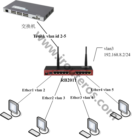
下面我们以RB2011Ui路由器为例,如何在RouterOS里基于交换芯片配置VLAN的trunk和access,在这个实例中,sfp1接口作为trunk口,上联一台管理交换机,ether1-ether4作为access口

首先将各个接口添加到一个交换组,RouterOS v6.41前,通过master-port设置,如sfp1作为master-port
/interface ethernetset name=ether1 master-port=sfp1set name=ether2 master-port=sfp1set name=ether3 master-port=sfp1set name=ether4 master-port=sfp1
RouterOS v6.41后配置取消了master-port,由bridge取代:
/interface bridge
add name=bridge1 protocol-mode=none
/interface bridge port
add bridge=bridge1 interface=ether1 hw=yes
add bridge=bridge1 interface=ether2 hw=yes
add bridge=bridge1 interface=ether3 hw=yesadd bridge=bridge1 interface=ether4 hw=yesadd bridge=bridge1 interface=sfp1 hw=yes
设置VLAN模式到各个接口,”vlan-mode=secure”将接口加入VLAN列表, “vlan-header=always-strip”用于access口,即去掉数据帧中的VLAN包头。
“vlan-header=add-if-missing” 对应trunk口,即添加VLAN包头到为标记帧中,”default-vlan-id” 为进入到access口的VLAN
/interface ethernet switch portset sfp1 vlan-header=add-if-missing vlan-mode=secureset ether1 default-vlan-id=2 vlan-header=always-strip vlan-mode=secureset ether2 default-vlan-id=3 vlan-header=always-strip vlan-mode=secureset ether3 default-vlan-id=4 vlan-header=always-strip vlan-mode=secureset ether4 default-vlan-id=5 vlan-header=always-strip vlan-mode=secure
添加VLAN列表条目,即指定包含VLAN ID的数据帧在那些接口通信
/interface ethernet switch vlanadd independent-learning=no ports=sfp1,ether1 switch=switch1 vlan-id=2add independent-learning=no ports=sfp1,ether2 switch=switch1 vlan-id=3add independent-learning=no ports=sfp1,ether3 switch=switch1 vlan-id=4add independent-learning=no ports=sfp1,ether4 switch=switch1 vlan-id=5
这里我们将介绍如何配置VLAN的三层管理IP地址,管理IP地址将通过trunk口到达路由器,并指定VLAN ID 3为管理接口
配置交换芯片与CPU连接,在RB2011有两组交换芯片,switch1和switch2,switch1管理sfp1,ether1-ether5,switch2管理ether6-ether10。因此这里需要注意,我们配置的是sfp1和ether1-ether4,所以选择的是switch1_cpu,设置 “vlan-header=leave-as-is” 原因是管理IP数据到CPU保持原有的标记(tag)模式。
/interface ethernet switch portset switch1_cpu vlan-mode=secure vlan-header=leave-as-is
修改VLAN列表条目,允许VLAN ID 3的数据能在sfp1,ether2和switch1_cpu,首先我们查看VLAN列表配置
[admin@MikroTik-J] /interface ethernet switch vlan> printFlags: X - disabled, I - invalid
 #   SWITCH                             VLAN-ID    PORTS 0   switch1                                  2      sfp1
                                                       ether1
 1   switch1                                  3      sfp1
                                                       ether2
 2   switch1                                  4      sfp1
 3   switch1                                  5      sfp1
                                                       ether4
找到VLAN id 3的对应序列号为#1,将VLAN id 3的配置加入switch1-cpu,注意这里用set命令是设置,而非把switch1-cpu添加入规则,因此我们的命令是所有的接口都要设置一次ports=sfp1,ether2,switch1-cpu如下,当然这winbox下可以直接通过图像界面添加。
[admin@MikroTik] /interface ethernet switch vlan> set 1 ports=sfp1,ether2,switch1-cpu[admin@MikroTik-J] /interface ethernet switch vlan> printFlags: X - disabled, I - invalid
 #   SWITCH                              VLAN-ID    PORTS 0   switch1                                  2      sfp1
 1   switch1                                  3      sfp1
                                                       ether2
                                                       switch1-cpu
 2   switch1                                  4      sfp1
                                                       ether3
 3   switch1                                  5      sfp1
                                                       ether4
以上VLAN交换芯片菜单配置完成后,进入interface vlan菜单,添加三层接口的VLAN,这里需注意master-port从switch-cpu接收所有的数据,因此三层VLAN接口配置必须是master-port,即master-port是sfp1,配置管理IP地址192.168.8.2/24到vlan3接口上。
/interface vlanadd name=vlan3 vlan-id=3 interface=sfp1/ip addressadd address=192.168.8.2/24 interface=vlan3
2023-12-13T11:46:19
2023-12-13T11:48:22
2024-01-02T09:07:42

2024-01-02T09:07:20

2024-01-02T09:06:50

2024-01-02T09:06:26

2024-01-02T09:06:01

2024-01-02T09:05:20

2024-01-02T09:04:49

2024-01-02T09:04:17