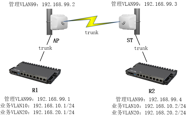
从RouterOS v6.41开始,提供了Bridge的VLAN filtering功能,Bridge能完全实现vlan的控制,下面的两个事例基于无线网桥vlan透传的配置
如下面的事例,需通过无线网桥转发3个不同的VLAN ID(trunk),VLAN 10和20是业务VLAN,VLAN99作为所有设备的管理VLAN:

首先从创建新的bridge接口开始,并将ether1和wlan1接口加入bridge,配置适用于AP和ST设备:
/interface bridgeadd name=bridge protocol-mode=none/interface bridge portadd bridge=bridge interface=ether1add bridge=bridge interface=wlan1
通常RSTP在点对点网桥中不会启用,因为这样的点对点网络不会行成环路,除非你的方案要求用RSTP协议,实现环路保护,如多路径的备份链路。
出于VLAN安全考虑,应该启用ingress-filtering(vlan入口过滤),因为只期望通过tagged VLAN 通过,untagged的vlan禁止通过,下面配置适用于对AP和ST:
/interface bridge portset [find where interface=ether1 or interface=wlan1] frame-types=admit-only-vlan-tagged ingress-filtering=yes
配置bridge vlan,由于VLAN 99作为所有设备的管理VLAN,需允许这个VLAN ID能够访问CPU(bridge),否则在启用Bridge的VLAN filtering后,将无法访问网桥设备。VLAN10和20不需要访问CPU,只需trunk到到另一端。在AP和ST上都添加相同的VLAN配置:
/interface bridge vlanadd bridge=bridge tagged=ether1,wlan1 vlan-ids=10add bridge=bridge tagged=ether1,wlan1 vlan-ids=20add bridge=bridge tagged=ether1,wlan1,bridge vlan-ids=99
R1、R2、AP和ST设备都需要创建一个三层管理VLAN接口,以便能够通过VLAN99访问设备,(警告:如果启用Bridge的VLAN filtering后,没有打通三层VLAN,所有bridge端口将丢是对设备管理,包括winbox的MAC登录。
AP和ST需在Bridge接口上创建三层VLAN接口,并配置IP地址,AP的VLAN99管理IP配置如下:
/interface vlanadd interface=bridge name=MGMT vlan-id=99/ip addressadd address=192.168.99.2/24 interface=MGMT
ST的管理IP配置如下:
/interface vlanadd interface=bridge name=MGMT vlan-id=99/ip addressadd address=192.168.99.3/24 interface=MGMT
如果要允许更多的VLAN被转发,只需要在bridge vlan中指定更多的VLAN id规则。
设置AP的无线连接配置,配置wpa2的安全加密规则取名wlan_sec
/interface wireless security-profilesadd authentication-types=wpa2-psk mode=dynamic-keys name=wlan_sec wpa2-pre-shared-key=use_a_long_password_here
配置AP设备模式为bridge,设置ssid为ptp_test,选择安全策略为wlan_sec,其他参数如下:
/interface wirelessset wlan1 band=5ghz-a/n/ac channel-width=20/40/80mhz-Ceee disabled=no mode=bridge scan-list=5180 security-profile=wlan_sec ssid=ptp_test
设置ST配置wpa2的安全加密
/interface wireless security-profilesadd authentication-types=wpa2-psk mode=dynamic-keys name=wlan_sec wpa2-pre-shared-key=use_a_long_password_here
配置ST设备模式为station-bridge,设置ssid为ptp_test,选择安全策略为wlan_sec,其他参数如下:
/interface wirelessset wlan1 band=5ghz-a/n/ac channel-width=20/40/80mhz-Ceee disabled=no mode=station-bridge scan-list=5180 security-profile=wlan_sec ssid=ptp_test
以上无线配置,采用普通的802.11协议,如果需要更高效的带宽传输,可以选择MikroTik私有的NV2协议。
对于R1和R2的路由器,在这个事例中,VLAN传输止步于两台路由器,AP和ST都分别接入两台路由器的ether2口,因此直接在ether2网口配置三层vlan子接口,R1接入ether2配置如下
/interface vlanadd interface=ether2 name=MGMT vlan-id=99add interface=ether2 name=vlan10 vlan-id=10add interface=ether2 name=vlan20 vlan-id=20
添加R1管理IP地址:
/ip addressadd address=192.168.99.1/24 interface=MGMT
R1配置vlan10和vlan20的IP地址
/ip addressadd address=192.168.10.1/24 interface=vlan10add address=192.168.20.1/24 interface=vlan20
R2的路由器接入ether2配置三层vlan接口如下
/interface vlanadd interface=ether2 name=MGMT vlan-id=99add interface=ether2 name=vlan10 vlan-id=10add interface=ether2 name=vlan20 vlan-id=20
添加R2管理IP地址
/ip addressadd address=192.168.99.4/24 interface=MGMT
R2配置vlan10和vlan20的IP地址
/ip addressadd address=192.168.10.2/24 interface=vlan10add address=192.168.20.2/24 interface=vlan20
当无线连接成功后,确保三层管理VLAN配置正确,最后在AP和ST开启bridge接口下的 VLAN filtering,因为AP设备通常只有一个以太网口,没有配置console口,如果一旦丢是管理,只能复位操作。
/interface bridgeset bridge vlan-filtering=yes
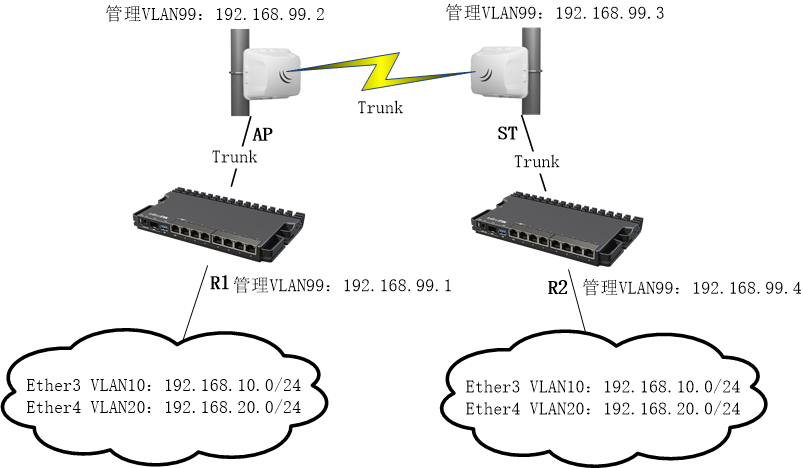
根据上面的事例,网络结构进行变动,需要经过路由器将VLAN传递给两端的局域网,即无线网络打通远端的vlan10和vlan20的网络,在这个事例中 R1和R2的ether3和ether4分别对应vlan10和vlan20,配置为access口,这里的R1和R2路由器变成了二层交换机。

在这个事例中AP和ST继续作为无线网桥trunk vlan10、20和99,因此配置不变,仅修改R1和R2的配置。
首先创建Brdge接口,加入ether2,ether3和ether4,两端网桥设备仍然接入路由器的ether2口,两台路由器R1和R2配置相同:
/interface bridgeadd name=bridge protocol-mode=none/interface bridge portadd bridge=bridge interface=ether2add bridge=bridge interface=ether3add bridge=bridge interface=ether4
设置ether2只能通tagged标签,ether3和ether4设置pvid为10和20,即access端口,两台路由器R1和R2配置相同:
/interface bridge portset [find where interface=ether2] frame-types=admit-only-vlan-tagged ingress-filtering=yesset [find where interface=ether3] pvid=10set [find where interface=ether4] pvid=20
配置vlan trunk,ether2上trunk vlan10、20和99,同时vlan99传递给bridge(CPU处理),两台路由器R1和R2配置相同:
/interface bridge vlanadd bridge=bridge tagged=ether2,bridge vlan-ids=99add bridge=bridge tagged=ether2 vlan-ids=10add bridge=bridge tagged=ether2 vlan-ids=20
创建管理vlan99的三层接口,在R1配置
/interface vlanadd interface=bridge name=MGMT vlan-id=99
添加R1管理IP地址
/ip addressadd address=192.168.99.1/24 interface=MGMT
创建管理vlan99的三层接口,在R2配置
/interface vlanadd interface=bridge name=MGMT vlan-id=99
添加R2管理IP地址
/ip addressadd address=192.168.99.4/24 interface=MGMT
以上配置完成
2023-12-13T11:46:19
2023-12-13T11:48:22

2024-01-12T09:12:31
2024-01-12T09:12:03
2024-01-11T09:02:33

2024-01-11T09:02:06

2024-01-11T09:01:40

2024-01-11T09:01:11

2024-01-11T09:00:46

2024-01-11T09:00:12